Assembly
Assembling the AMI-System
Connecting Camera and Light Ring
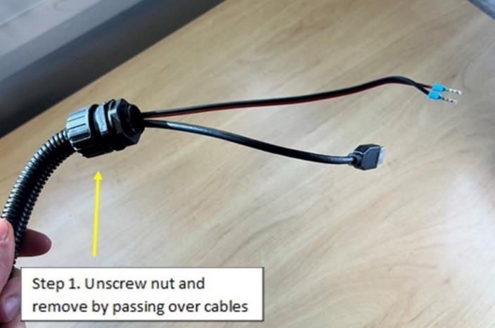
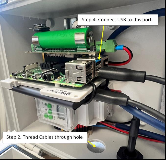
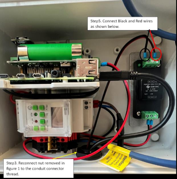
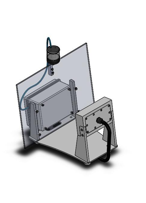
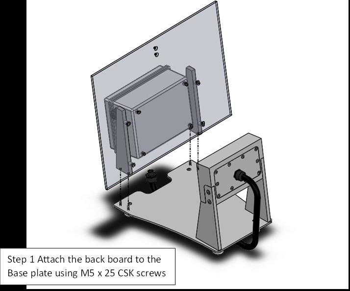
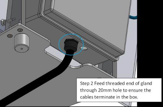
The camera and lighting cables can be seen the figure above. They are coming out of the end of the protective conduit from the back of the camera box. To thread and connect the cables into the electronics box and connect the conduit to the box, please follow the steps below:
- Following the cable coming out of the back of the camera box, unscrew and remove the thin black plastic conduit connector nut (step 1 in the figure).
- Thread the USB and power cables through the hole in the electronics box (step 2 in the figure).
- Push the conduit and connector as far into the hole (same as step 2) as it will go, then replace the nut removed in step 1, passing it over the USB and power cables, then screwing it onto the conduit connecting until tight, this should be slightly more than hand tight so use a spanner (step 3 in the figure).
- Connect the USB into the port shown in the figure (step 4 in the figure).
- If your AMI-System has a black voltage regulator on the right, then you need to connect the black and red exposed wire to the upper right terminal of the voltage regulator (step 5 in the figure). To do this use a small flathead screwdriver to unscrew the screw on the front of the terminal. Place the metal part of the wires in the holes - black wire into the left (0V) slot and red wire into the right (+Vo) slot - then screw tight again. Once tightened give the wire a light tug to check it is securely in place. If your AMI-System does not have a voltage regulator, then connect the black and red exposed wires to a black and a red terminal block at the bottom-centre of the electronics box instead.
-
To connect the LepiLED or UV-light tube (depending on the AMI-System you have):
- Feed the LepiLED/UV-light cable through the gland on the right side of the electronics box.
- Screw the nut on the inside of the box to tighten. Also screw the cap on the outside of the box tight.
- Connect the brown and blue wires to the right-hand side of the bottom red and black terminal block. Blue neutral wire into black terminal, brown live wire into red terminal. To do this use a small flathead screwdriver to unscrew the screw on the front of the terminal block. Place the metal part of the black wire in the hole on the right side of the terminal block and then screw tight again, once tightened give the wires a light tug to check they are securely in place. Note this step can be fiddly.
Connecting to Power – Benchtop and/or Battery Box
-
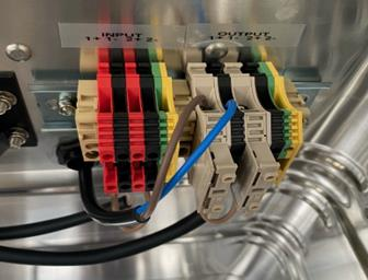
A cable extends from the bottom of the electronics box and
terminates in two wires: one brown and one blue.
- If using the battery box, these should be passed through the hole in the back of the battery box and connected to the DIN rail mounted terminals, labelled Output 1+ (brown cable into beige plastic terminal which will have to be flipped up) and Output 1- (blue cable into black plastic terminal, see figure). Fasten using a small flat head screwdriver.
- If using a benchtop power supply or a 12 V wall plug, connect the terminal wires - brown to the positive output terminal (usually red), blue to negative output terminal (usually black). The power supply should be set to just above 12 V (e.g. 12.5 V) and just above 2 A (e.g. 2.5 A). If using a 12 V wall plug, it should be rated at 2.5 A or more.
-
To turn the system on, press the
MAN(-)key until the text at the bottom of the screen saysON ON. -
To turn the system off, press the
MAN(-)until the text readsOFF OFF.
Note: When the AMI-System
is in the field, set it to AUTO OFF, so that it
follows the programme. When it turns on at the set times, it will
read AUTO ON. Therefore, if you are deploying the
AMI-System when it is scheduled to be on, you will be setting it
to AUTO ON (there will be no option for
AUTO OFF).
Connecting to the Raspberry Pi
The Raspberry Pi is the computer that controls the AMI-System. It is located in the electronics box at the back of the AMI-System. Ensure that a microSD card is inserted into the left of the Raspberry Pi. The microSD card contains the operating system and software for the AMI-System. The Raspberry Pi is powered by the electronics box, so it will turn on when the AMI-System is turned on.
The simplest way to use the Raspberry Pi is to use the AMI Bluetooth App on an Android phone when the AMI-System is powered on. After connecting, you can use it to:
- Check if camera and SSD are connected,
- Check if it is taking pictures,
- Check the time and date and set it if necessary (do this at least once after setting the system up),
- Check the SSD's storage space, and
- To set the interval in which pictures are taken (the default is 10 seconds, but we recommend to change this to 60 seconds).
Setting the Timer Relay
Find the complete manual for the timer relay in the manufacturer's documentation. Instructions for the most common settings are provided below.
Set Time on Timer Relay
-
Press the
Clockkey and theMANkey simultaneously to toggle between 12/24-hour clock mode. -
Keep the
Clockkey pressed and then press theD+key to set the day. -
Keep the
Clockkey pressed, then press theH+key to set the hour.00–23in24-hourmode.01–12in12-hourmode.
-
Keep the
Clockkey pressed, then press theM+key to set the minutes. - Click the
MANbutton to return to the main screen.
Set a Schedule
- Press
PRto set the schedule for when AMI-System will turnON. -
Press
D+stepwise for day selection as given below.MO TU WE TH FR SA SU(All weekdays).MO TU WE TH FR SA(Exclude Sunday).MO TU WE TH FR(Exclude Weekends).MO TU WE TH(Exclude Friday & Saturday).SA SU(Only Weekends).FR SA(Only Friday & Saturday).TU WE TH FR SA SU(Exclude any single day).MO/TU/WE/TH/FR/SA/SU(Include Single day).MO WE FR(Exclude Alternate day).TU TH SA(Exclude Alternate day).
-
Press
H+to edit and increment the hour. Use theMAN(-)key to decrement hours. - Press
PRto set the schedule for when AMI-System will turnOFF. -
Press
D+stepwise, as above, for day selection. Please note that theOFFday will be the day after theONday as it passes00:00. For example, if theONschedule isMO WE FR, theOFFschedule should beTU TH SA. - Press
H+to set the hour. - Press the
Clockbutton to set the schedule. -
Press
MAN(-)to set AMI-System toOFF OFFuntil you set the AMI-System up in the field, where you will need to set it toAUTO OFF. Note: This will sayAUTO ONif you are currently within the programmedONperiod.
Set-up
Checks Before Deployment
-
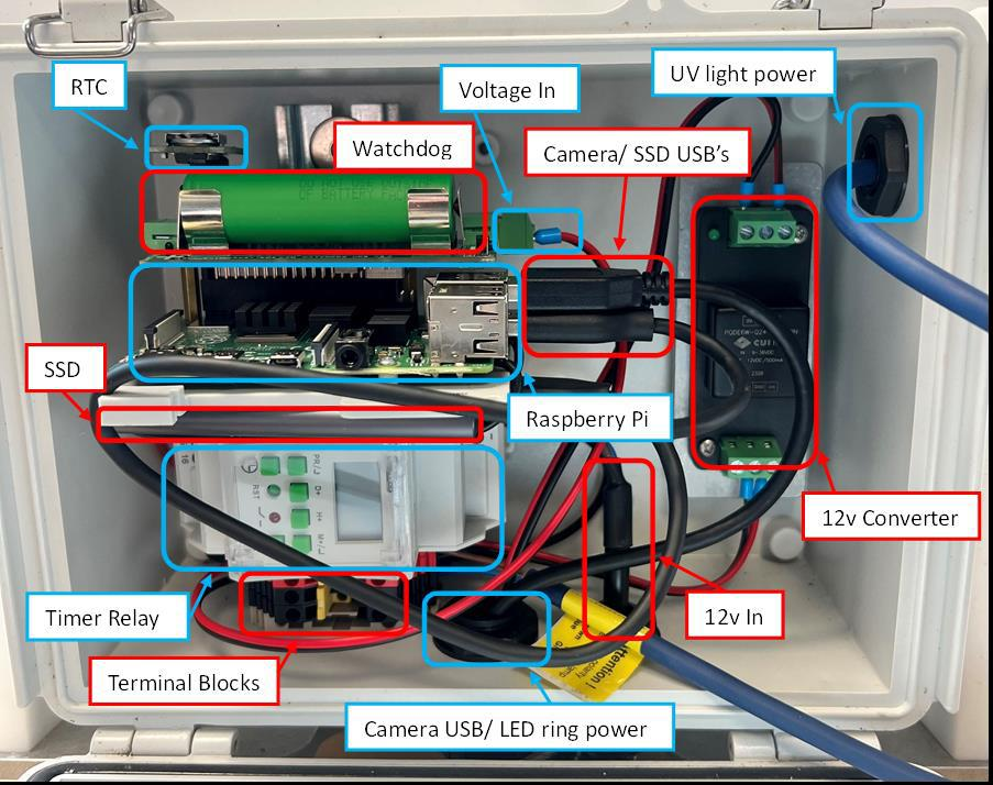
Check that everything within the grey electronics box at the back
of the AMI-System is plugged in and all wires are secure. The box
should include:
- SSD,
- MicroSD card inserted into the left of the Raspberry Pi,
- Watchdog/UPS battery (18650 lithium-ion battery), and
- RTC battery (CR1220 button battery)
- Check that solar cables are crimped, ready for use.
- Ensure that all openings and glands are properly sealed. If not, apply sealing, e.g., silicon or hot glue, to ensure weatherproofing.
Equipment List
General
AMI-System
Solar
*Recommended: 120 Ah 12 V Absorbed Glass Mat (AGM) Lead Acid deep cycle or Marine Lead Acid Battery.
**Recommended: 100 W solar panels in parallel (12 V panels) – Max open circuit voltage (Voc) 25 V, max short circuit current (Isc) 25 A.
Solar Panel Set-up
Put Together Solar Rigging
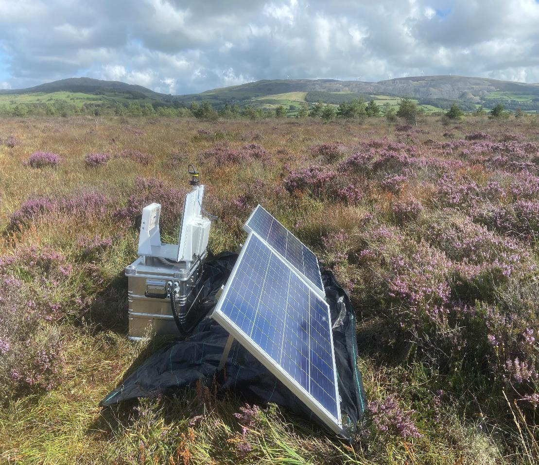
- Clear an area large enough to contain the solar panels and AMI-System.
- Lay down the matting and pin it down; use a hammer if needed.
- [Add own instructions for solar rigging set up]
Attach Solar Panels to Rigging
- [Add own instructions]
AMI-System Set-up
Screw AMI-System to Box and Connect (Should Be Done Before Connecting to Power)
- The feet of the AMI-System have screw holes. Put the AMI-System on the lid of the box and line up the holes in the AMI-System feet with the holes in the metal box lid.
- Use a black rubber washer, followed by the silver metal washer and screw to attach the AMI-System to the box using the ¼ inch Allen key. Having a battery in the battery box while completing this step is helpful because it acts as a counterweight.
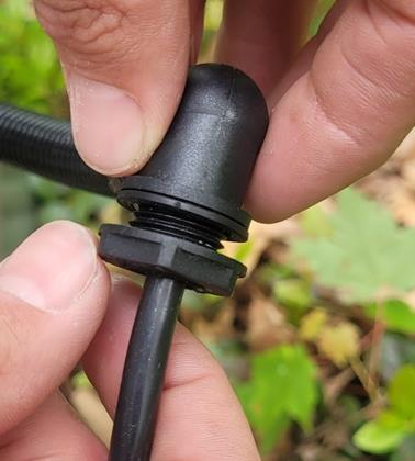
- The wire coming out of the back of the AMI-System, with blue and brown ends, should have conduit and a conduit connector nut. Unscrew the nut and feed the wires through the hole at the back of the battery box.
- Once through, screw the nut back tightly on the inside of the box, securing the wires in position.
- Inside the metal box, attach the blue and brown wires to the ‘LOAD’ fuses. Flip up the “door” of the brown (+1) terminal and loosen the screw with the small flathead screwdriver. Insert the brown wire into the brown terminal (+1) and tighten the screw until the wire is secure. Repeat with the blue wire in the black (-1) terminal.
- Attach the white landing board to the back board of the AMI-System with clips.
Note: If the fuse head is lifted up, the power is disconnected.
Connect Batteries
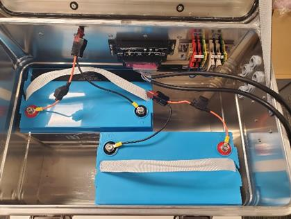
- Connect the battery wires to the batteries. The red wire goes to the positive terminal and the black wire to the negative terminal. Put the washer on first, followed by the metal loop at the end of the battery wire, another washer, and finally the nut. Tighten with the 13 mm socket. It is safer to complete the negative terminal first.
- Repeat with the second battery.
- Place the two batteries in the aluminium battery box, facing the same way.
- Connect the battery wires to the wires leading to the SunSaver via the brown connectors.
- The battery status LED on the SunSaver should turn green.
Connect Solar Panels
- The two solar panels will each have a male and female terminal. Connect the two female terminals with a female connector and the two male terminals with a male connector.
- Add conduit to the two black cables, together or separately. Mark the positive and negative ends before adding the conduit, or use a multimeter to identify them.
- Connect the two black cables to the solar panels via the female and male connectors.
- Pass the two black cables, ending in naked wires, through the grey glands on the side of the battery box.
- Connect the wires to the ‘SOLAR’ fuses on the DIN rail by loosening the screw with the flathead screwdriver and inserting the wire into the terminal. Connect the positive end to the +1 output and the negative end to the -1 output. Tighten the screws until the wires are secure.
- Use Velcro or cable ties to secure loose wires and cables to the metal pole of the solar rig.
- If the system is working, a green light should appear in the AMI-System box to show that the batteries are connected and fully charged.
Checks in Field: Before You Leave the AMI-System, Please Check the Following
-
Within the battery box, check the solar status light on the
SunSaver DL.
- If there is no colour, but it flickers every 5 seconds, it is not charging and has not been connected properly.
- If it is solid green, with occasional flickers, it is charging.
- If it is red, there is an error.
-
Check the battery status lights on the SunSaver DL.
- If it is green, the battery is full or nearly full.
- If it is yellow, the battery is half full.
- If it is red, the battery is low (flashing) or empty (solid).
-
Turn on the AMI-System at the timer relay.
- Check that the red light on the timer relay comes on.
- Check that the LepiLED/UV-light comes on.
- Use the AMI Bluetooth App on an Android phone to check if the camera and SSD are functioning correctly, and the time and timezone of the AMI-System are correct, and the AMI-System is taking pictures.
- Turn the timer relay back to
AUTO OFF.
Maintenance
Check the AMI-System
- Check that the timer relay is reading the correct time.
- Clean the solar panels to remove any dirt and leaves.
- Clean the white board with water, if dirt builds up.
- Check inside the grey box at the back of the AMI-System and inside the main aluminium box for water ingress and insects to ensure it is still fully sealed.
- Check there is no damage to the wires between the AMI-System and the solar panels/mains power source.
-
Check that the LepiLED/UV-light is working by pressing
MAN(-)until the screen displaysON ON. Remember to return it toAUTO OFFby continuing to pressMAN(-). - Replace the desiccant bag in the battery box, if needed.
Changing the SSD
Every few weeks, you will need to change the SSD. You can change it less often if needed, but you this will increase the amount of data to be uploaded. The SSD is located above the timer relay and plugged into the Raspberry Pi.
-
You can only change the SSD when the system is switched off.
Therefore, check on the timer relay that it is on
AUTO OFF.-
If not, please turn the system by pressing
MAN(-)until the screen displaysOFF OFFand wait until the lights on the Raspberry Pi stop flashing.
-
If not, please turn the system by pressing
-
Unplug the SSD from the Raspberry Pi and plug it into your
computer. Open the folder containing the images and check that it
has been populated and that the images look correct. Check the
following:
- Are the images lit evenly?
- Are images in focus?
- Are there any obstructions that you would be able to remove? For example, long pieces of grass.
- Is the metadata correct? Have the pictures been taken at the right time?
- Bring back the SSD for data upload.
- Plug in an empty SSD into the AMI-System.
- Make sure all SSDs have been correctly labelled.
Take-down
In the Field
-
Turn off the AMI-System on the timer relay by pressing
MAN(-)until it readsOFF OFF. - Remove and label the SSD.
- Open the aluminium battery box and unplug the batteries.
- Unscrew the solar wires from the terminals on the DIN rail with a flat-headed screwdriver and pull the wires out of the battery box.
-
Unscrew the wires connecting the AMI-System to the battery box using a
flat-headed screwdriver.
- The brown load fuse will need to be flipped up to gain access to the correct screw.
- Pull the wires out of the battery box. A conduit connector nut on the inside of the battery box will need to be unscrewed first.
- Using the allen key to undo the screws attaching the AMI-System to the top of the battery box. This must be done with care, as the AMI-System can easily fall to the ground as the last screw is removed.
- Remove the batteries from the battery box.
- Before removing the solar panels from the rigging, unlatch the 2x female connectors and 2x male connectors. Use the plastic wrench usually provided with solar connectors, or tweezers.
- Remove the solar panels.
- Take down the rigging and matting.
Storage
- The AMI-Systems should be stored indoors and upright.
- Remove the watchdog/UPS battery from the electronics box at the back of the AMI-System. Charge if needed.
-
Check the charge (voltage V) and capacity (ampere-hours Ah) of the
car batteries.
- Charge if needed.
- Recondition if needed (under 60% of original Ah). If it is below 50% Ah and reconditioning does not improve this, the battery cannot be used to power the AMI-System.
Troubleshooting
Hardware
Power
If the Raspberry Pi is not turning on and the timer relay light is not on, there might be a problem with the power source, connection, or fuse.
- Connections: Check that all connections are secure, especially the stepdown cable connecting the terminal block and the watchdog/UPS.
-
Fuse: Check that the “door” on the beige
Output 1+terminal in the battery box is tightly closed and holds a fuse when flipped up. Replace a missing or blown fuse using one of the spares in the plastic pocket attached to the SunSaver 20L. -
Power source: Within the battery box, inspect
the SunSaver 20L.
- If the battery status LED is red, the battery is empty or low. If there is no light, the battery has not been connected properly.
- If the solar-panel status LED is red, either flashing or solid, there is an error with the panels.
- If all status LEDs are green but the Raspberry Pi remains off, use a multimeter to find where power is interrupted. Test the solar, battery, and load circuits.
-
Check that the solar wires lead to the correct terminals:
positive to
1+and negative to1-.
LepiLED/UV-light
If the LepiLED/UV-light or ring lights are not turning on, you should check the connections at the back of the camera/lighting box. You can do this by carefully unscrewing the gland and seeing if any of the wires are slack, especially the larger black cable which is a USB-C cable connecting the camera. This can be plugged back in, if it has come loose. You should also check that the USB-C cable and the two wires connecting the camera and lights are securely connected to the Raspberry Pi in the electronics box.
Software
Camera
If the images are grey, and it says unable to connect, make sure that the camera USB-C cable is connected properly.
Time/Date
If the timestamps on the images are wrong, revise the instructions about setting the Real Time Clock.
SSD
In the scenario where the AMI-System is turned on and the SSD is not connected, or the Raspberry Pi, for some reason, does not detect the drive, the system will save images to the SD card rather than the SSD. To fix this we need to check if images have been saved to the SD card and remove them, and then check that we can get the SSD connected properly.
FAQ
Find common symptoms and solutions below. Start with what you can see, follow the checks in order, and stop where a trained technician is required.
Showing all troubleshooting topics.
Start here
Five-minute first check: what should I inspect before deeper troubleshooting?
Materials
- Phone or camera for photographs
Steps
- Look for water, corrosion, loose plugs, chewed cables, insects, mould, or burnt components. Do not power visibly wet or damaged electronics.
- Set the timer relay temporarily to ON ON. Note whether its red output light, the LepiLED/UV-light, camera ring, watchdog/UPS LED, and Raspberry Pi LEDs operate.
- Record exactly what works. A component-by-component record is more useful than “the AMI is broken”.
- After testing, return the timer to AUTO OFF, or AUTO ON if currently inside the programmed survey period.
Review AMI builds differ. Compare your electronics box with your own unit rather than assuming every photograph in an older manual matches.
What do OFF OFF, ON ON, AUTO OFF, and AUTO ON mean?
- OFF OFF: manually forced off. Use before handling SSDs or wiring.
- ON ON: manually forced on. Use briefly for tests.
- AUTO OFF: automatic schedule enabled and currently outside an ON period.
- AUTO ON: automatic schedule enabled and currently inside an ON period.
Press MAN(-) repeatedly to cycle states. Do not leave a deployed system in ON ON unless continuous operation is intentional.
Power, batteries, solar, and fuses
Nothing turns on: no timer light, no LepiLED/UV-light, and no Raspberry Pi lights
Likely causes
- Disconnected or exhausted main batteries
- Open, missing or blown output fuse
- Loose battery, solar-controller or load wiring
- Timer relay not supplying the electronics box
Steps
- Set the relay to OFF OFF.
- Check red battery leads are on positive terminals and black leads on negative terminals. Tighten with the appropriate socket.
- Check the beige/brown Output 1+ fuse “door” is fully closed and contains an intact fuse. Check the inline fuse in the red battery cable - the metal wire inside the plastic should be a continious U-shape.
- Read the SunSaver indicators. No battery light can mean the battery is not connected; red indicates low or empty battery. A red solar indicator indicates a solar-side error.
- With a two-lead multimeter in DC voltage mode, measure progressively from battery terminals, controller battery input, controller load output, timer output, and electronics-box input. The first point where voltage disappears isolates the faulty section.
- Do not use a non-contact AC detector pen. The AMI-System uses low-voltage direct current and such a pen may not detect it.
The solar charger says “charging”, but the batteries stay empty
- Clean leaves, dirt, and grime from both solar panels.
- Check for dense shade and seasonal changes in the sun path. A location that is bright enough to see may still be far too shaded for useful charging.
- Confirm both panels and their parallel connectors are intact and the positive and negative leads reach the correct solar terminals.
- Check battery voltage. Around 12 V can indicate a deeply depleted nominal 12 V lead-acid battery; while charging, a full battery may show around 14 V.
- If batteries have remained fully discharged for a long period, their capacity may have deteriorated. Charge and capacity-test them off-site, or substitute known-good matched batteries.
- For reliable operation, relocate panels to a sunnier position if cleaning and wiring checks do not restore charging.
Review Exact voltage interpretation depends on battery chemistry, load and charging state.
Can I deploy with one car battery? What battery type should I use?
- One nominal 12 V battery can be adequate for a short bench test, but is not the preferred field arrangement for repeated overnight operation.
- Marine, leisure, camping or deep-cycle AGM lead-acid batteries tolerate repeated charge and discharge better than ordinary starter batteries.
- The manual recommends two fully charged 12 V batteries, typically around 120 Ah each.
- If charging one battery off-site, charge the paired battery to a similar state before reconnecting. A large state-of-charge difference can cause a high equalisation current and may blow a fuse.
- Use a charger suitable for the actual battery chemistry and rating.
The timer relay flickers or the whole system starts and immediately dies
- Suspect very low main-battery voltage first. Check both batteries and the SunSaver battery indicator.
- Check that the load fuse holder is closed and cables cannot move in their terminals.
- Check the black and red input wires between the lower terminal area and the watchdog/UPS.
- Power the Raspberry Pi and watchdog separately from a suitable USB power bank only as a brief isolation test. If each works alone, suspect the 12 V to 5 V power path or its cable.
- If a watchdog has a temperature probe, overheating is possible but was considered an unusual cause. Allow the enclosure and probe to cool before retesting.
A fuse is blown, missing, or its brown/beige holder is broken
- Turn the relay OFF OFF and disconnect battery power.
- Open the fuse holders and inspect the fuse. You can test a cylindrical fuse from the brown/beige holder with a multimeter in resistance/continuity mode. A battery inline fuse has failed if its internal U-shaped conductor is broken.
- Replace only with the same known type and rating.
- If the DIN-rail holder itself is broken, some boxes contain an unused spare holder labelled for another output. Swap only if you are competent and preserve polarity and terminal positions.
- After reconnection, power up briefly and watch for heating or immediate fuse failure.
Raspberry Pi, watchdog/UPS, and connections
The Raspberry Pi has no lights, but the LepiLED/UV-light or ring light works
Isolation test
- Confirm the timer relay red output light is on. If it is off, troubleshoot the battery box and relay first.
- Inspect the 12 V to 5 V step-down cable and connections to the watchdog/UPS.
- With all main power isolated, briefly power the Pi by its normal USB power input from a suitable power bank. If its LEDs remain off, suspect the Pi.
- Briefly power the watchdog/UPS by its supported USB input. If its LED remains off, suspect the watchdog.
- If Pi and watchdog each work separately, suspect the step-down cable or power-path wiring.
- If a second AMI is available, swapping one known-good component at a time can isolate the fault. Label everything and never swap multiple parts simultaneously.
How do I interpret the watchdog/UPS green LED?
- About once per second: normal self-test indication.
- Rapidly, about five times per second: hardware error.
- No flashing: no power, powered down state, or fundamental fault.
- Solid: can indicate the watchdog has reset the Pi.
The LED pattern is diagnostic evidence, not absolute proof. A cable that appears intact can still have no electrical continuity.
The watchdog turns the Raspberry Pi off shortly after startup
- Check the main battery supply reaches the watchdog continuously.
- Check and, if necessary, charge or substitute the 18650 backup cell.
- Inspect the step-down cable for broken continuity, even if it looks undamaged.
- Check the watchdog LED pattern.
- If the unit has a temperature sensor and has been heated by direct sun, cool it and retest.
The watchdog is intended to shut down the Pi safely when main power disappears or its backup battery becomes too low.
The Raspberry Pi red LED flashes or shows an unusual blink pattern
- Record a clear video long enough to identify the repeated pattern.
- Check whether the microSD card is fully inserted.
- Try a known-good AMI-System microSD card or re-image a spare card with the approved AMI-System operating-system image.
- If the behaviour changes when the RTC is attached, stop and check. (“RTC” means the small blue clock board.) A shorted accessory can suppress power.
- If the Pi still shows a fault using a known-good power supply and microSD card, the Pi itself may require replacement.
No HDMI picture appears on the monitor
- Do not assume the Pi has failed. Some AMI-Systems repeatedly failed to display over HDMI while otherwise working.
- Connect the HDMI lead before powering the Pi.
- Check the Pi power LED and microSD card.
- Prefer Ethernet and SSH for configuration.
- Low supply voltage can affect peripherals such as HDMI before the rest of the system stops.
How do I connect by Ethernet and SSH?
- Connect an Ethernet cable between the AMI-System Pi and laptop.
- Turn the AMI-System to ON ON and wait for the Pi to boot.
- Open Command Prompt, PowerShell, or Terminal.
ssh pi@raspberrypi.local- Accept the host prompt if shown.
- Enter the AMI-System password supplied with the unit. No characters will appear while typing.
If you typed raspberry.local, correct it to raspberrypi.local. If the host
still
cannot be resolved, check Pi power and the Ethernet connection. Organisational network restrictions may
also
interfere.
How do I replace or upgrade the Raspberry Pi OS microSD card?
- Set the timer relay to OFF OFF and wait until all Pi activity has stopped.
- Remove the microSD card from the Pi.
- Insert the prepared replacement card.
- Turn the system on and allow extra time for the first boot.
- Check SSH or the Bluetooth app, then verify camera, SSD, time zone, RTC, and capture interval.
- Take and inspect test images before deployment.
Camera, ring light, and LepiLED/UV-light
Images are grey or the camera says it cannot connect
- Check the camera USB cable at the Pi.
- Unscrew the black rear cap of the camera housing carefully and check the USB-C end is fully inserted.
- Test camera detection in the AMI Bluetooth App or using the command line and SSH:
ls /dev/video0ls -l /dev/v4l/by-id/- If the device exists, the Pi detects a camera.
- If the AMI Bluetooth App says "No Camera" or “No such file or directory” appears on the command line, suspect the cable, connector, or camera.
- Plug the camera USB lead into a laptop. If the laptop recognises a Logitech camera, the camera and cable path are at least partly functional.
- If necessary, test the long USB cable with another known-good USB device, then test the camera using another known-good USB-A to USB-C lead. This will help determine if the issue is with the cable or the camera.
- If the camera is detected but images remain grey, inspect the Motion log (downloadable via the AMI Bluetooth App) and camera-device path.
The camera ring light does not turn on or flickers briefly
The ring light is powered by separate wires, not by the camera USB cable.
- Set the timer relay to OFF OFF and inspect the red/black or brown/blue light wires in the electronics-box screw terminals.
- Gently tug each wire to confirm it is clamped.
- Inspect the cable along its whole route for animal bites, crushing or water damage.
- If the conductors are secure at the box but the light still fails, a break or solder fault inside the camera housing may require substantial disassembly and soldering.
- Do not continue a survey with failed illumination unless the study protocol explicitly allows it.
The LepiLED / attractive UV light does not turn on
- Set the relay briefly to ON ON and check whether the timer relay output light is on.
- Check the LepiLED cable gland is tight and dry.
- With power isolated, verify the blue/black neutral wire and brown/red positive wire are firmly clamped to their intended terminals.
- Inspect the external light and cable for bites, impact or water ingress.
- If other loads work and the LepiLED/UV-light does not, record voltage at the light output using a multimeter. If voltage is present, the LepiLED/UV-light may be faulty. If no voltage is present, check the wiring.
- Return to AUTO mode after testing.
No images are taken, even though the Pi, lights, and SSD appear on
- Confirm the camera is detected in the AMI Bluetooth App or in the terminal with
ls /dev/video0. - Confirm the SSD and mount point in the AMI Bluetooth App or in the terminal with
lsblk. - Start image capture with
sudo motionin the terminal. - Inspect the image folder and the Motion/camera log (downloadable from the AMI Bluetooth App or using the steps below in the terminal).
ls /media/pi/PiImagestail -n 100 /var/log/motion/motion.log
- If hardware checks pass but capture never starts, replace the AMI-System software microSD card with a known-good approved image.
Motion detection does not trigger when I wave in front of the board
Most AMI-Systems are intended to take pictures at fixed intervals. Many do not use motion-triggered capture because pixel-change detection can generate an unmanageably large number of images, especially in the tropics.
- Confirm the study protocol. Do not enable motion detection unless it is required.
- For normal fixed-interval operation, verify the configured snapshot interval instead.
- If motion capture is explicitly required, check Motion configuration and logs with technical support.
Images are blurry, poorly coloured or inconsistently focussed
- Place text and several colours on the landing board at the normal focal distance.
- Allow several images after startup. The first few can be blurry while settings take effect.
- Inspect focus, colour, exposure, evenness of illumination, and timestamp.
- Only change camera settings if test images are inadequate; AMI-Systems with different camera/light combinations may legitimately have different settings.
- Open the settings script:
sudo nano /home/pi/scripts/setCamera.sh
- Record original values before changing anything, adjust one parameter at a time, restart capture and compare images.
SSD, image storage, and missing data
The SSD is empty or no new photographs appear
- Check whether the SSD is recognised in the AMI Bluetooth App.
- Turn the relay to OFF OFF before reseating the SSD.
- Try a blue USB port and another known-good USB cable/port.
- Connect by SSH and run:
lsblkLook for a drive such as sda, commonly around 500 GB, mounted at
/media/pi/PiImages.
- Check the directory with
ls /media/pi/PiImages. - Connect the SSD to a laptop and verify it can be read and its volume label is PiImages.
- If it is not detected, substitute a known-good SSD or cable.
- Never remove or insert an SSD while the Pi is running.
Images were saved to the microSD card instead of the SSD
- Stop capture:
sudo pkill motion. - Inspect
/media/pi/PiImagesand determine whether the SSD is actually mounted there. A directory existing by itself does not prove which device supplies it. - Use
lsblkto verify the mount point. - If files are on the Pi's card, copy them to the laptop:
scp -r pi@raspberrypi.local:/media/pi/PiImages C:/Users/YourUsername/Documents/
- Open several copied files and confirm the backup.
- Only then remove an incorrect local directory if a technician has confirmed the diagnosis.
- Power down, connect the correctly labelled SSD, power up, and verify the mount with
lsblk.
Review Earlier manual wording about the existence of this path was disputed. The mount output, not path existence alone, must be used.
How do I copy the Motion log to a Windows laptop?
Use the AMI Bluetooth App or the command matching your terminal while connected via an ethernet cable.
Command Prompt
scp pi@raspberrypi.local:/var/log/motion/motion.log C:/Users/YourUsername/Downloads/
PowerShell
scp pi@raspberrypi.local:/var/log/motion/motion.log "C:\Users\YourUsername\Downloads\"
Replace YourUsername. If the file does not exist, first verify the software image and log
location.
The AMI-System stops taking images part-way through the night
- Check whether the whole system lost power: compare the final image time with timer schedule and battery state.
- Check free SSD space and whether the SSD remained mounted.
- Inspect
/var/log/motion/motion.logaround the final image time (downloadable from the AMI Bluetooth App or using an ethernet cable and SSH). - Check for intermittent camera disconnects and loose USB cables.
- Check UPS/watchdog shutdowns, low main-battery voltage, and solar charging.
- Substitute known-good SSD, camera cable, or software microSD one at a time.
- Do not assume the cause from the symptom alone. Similar cases were associated with power, storage, and software issues.
Time, RTC, and timer schedule
Image timestamps are wrong
- Connect using the AMI Bluetooth App or the command line over SSH and check time and timezone. If using the command line:
timedatectl- Set the correct region-based time zone if required, then set the system date and time using the approved Linux method.
- Once system time is correct, write it to the hardware clock:
sudo hwclock -w- Read it back:
sudo hwclock -r- After confirming the time is correct in the AMI Bluetooth App or the command line, power down for several minutes, restart, and check whether time was retained. If not, reseat the RTC and replace its CR1220 coin cell.
- Also set the separate timer relay clock. The Pi RTC and timer relay are independent.
The RTC board has come loose
- Turn OFF OFF and disconnect main power.
- Remove the watchdog's cylindrical battery only if necessary for access, noting polarity.
- Fit the small blue RTC board onto the six raised pins at the far left of the header, matching the known-good orientation.
- Do not offset the six-pin connector.
- Reinstall the coin cell and any removed battery with correct polarity.
- Boot, set time, run
sudo hwclock -w(if using the command line), then test time retention.
The timer relay displays bL0C and buttons do not work
The keypad lock is active.
- Press the clock and PR keys simultaneously for at least three seconds.
- Look for ULoC on the display.
- Check the relay clock and programmed ON/OFF events after unlocking.
How do I set a basic overnight schedule?
- Hold Clock and use D+, H+, and M+ to set current day, hour, and minute.
- Press PR to programme ON. Select survey days with D+, then set hour and minute using the relay instructions.
- Press PR again for OFF. If operation crosses midnight, the OFF day is the following day. For ON Monday/Wednesday/Friday, OFF is Tuesday/Thursday/Saturday.
- Press Clock to return.
- Leave the system in AUTO mode.
A schedule used in some projects is 18:30 to 04:00 on alternate nights. It is not universal. Start after proper darkness and stop before sunrise to avoid exposing resting insects to birds. Adjust for local latitude, season and study design. Review
What image interval should I use?
Fixed-interval capture is normal. One-minute intervals have been used for most AMI-Systems. Ten-second capture can create excessive data, and motion capture can be substantially more intensive.
- Follow the protocol for your project and region.
- Estimate storage and upload workload before shortening the interval.
- After changing it, inspect timestamps across a short test sequence.
Review Confirm the current approved project interval before deployment.
Bluetooth app and field configuration
The AMI-System does not appear in the Bluetooth app
- Confirm this AMI-System has a Bluetooth-enabled software image. Not every historical AMI-System does.
- Confirm the Pi is powered and has completed booting.
- Move within a few metres, enable Bluetooth, use a compatible browser/device, and rescan.
- If Ethernet works but Bluetooth does not, suspect an old or incorrect microSD image.
- If neither works, troubleshoot power and boot before app connectivity.
The Bluetooth app cannot connect to an unpowered Pi.
How can I use the Bluetooth app to obtain the camera log?
- Power the AMI-System and connect to it in the AMI Bluetooth app.
- Open the verbose or diagnostics section.
- Scroll to the camera/Motion log control and download the log.
- Save the file with the AMI-System ID, site, and date.
- If the Bluetooth app is not working, the software image may be older. Use SSH/SCP or fit an approved updated microSD card.
Water, wildlife, and environmental damage
There is water, condensation, rust, or mould inside a box
- Photograph water tracks, corrosion, and cable-gland condition.
- Remove standing water and allow thorough drying.
- Inspect Pi, microSD, watchdog, 18650 cell, RTC, timer, fuses, and cable connections for corrosion.
- Replace visibly damaged cells. Do not recharge swollen, rusty or leaking lithium-ion cells.
- Test Pi and watchdog separately with a power bank only after fully dry.
- Replace desiccant and correct the failed seal or gland before redeployment.
Water damage can create multiple simultaneous faults. Replacing a complete electronics box may be more reliable than piecemeal field repair.
Ants or other insects are nesting in the system
Ants and other insects can cause significant damage to electronic systems by creating nests, chewing through cables, and introducing moisture and debris.
Cables show animal bite marks or physical damage
- Do not energise a cable with exposed conductors.
- Photograph and label both ends.
- Replace the complete cable where practical rather than taping a field splice.
- For the camera cable, test camera and cable separately.
- For light wiring, note that conductors may be soldered inside the housing and repair may require disassembly.
- Add mechanical protection or reroute cables before redeployment.
The white landing board is mouldy, dirty or damaged
- Clean with water and a non-abrasive cloth.
- Remove grass and other obstructions visible in photographs.
- Replace a board that cannot be cleaned or held flat.
- Use a consistent white, matte replacement of similar dimensions. Avoid glossy or strongly textured material.
- Record the change because board material can affect image consistency and potentially insect response.
Pre-deployment and escalation
What complete test should I run before returning an AMI-System to the field?
- Visual inspection: dry, sealed, no corrosion, cables secure.
- Battery and solar: correct polarity, matched charge, green/expected controller status.
- Timer: correct local time, schedule, and AUTO state.
- Pi: boots, stable LEDs, SSH or app access.
- Watchdog: slow normal flash and safe shutdown when main power is removed.
- RTC: correct time retained over a power-off test.
- Camera: detected, test images clear, and correctly coloured.
- Lights: LepiLED/UV-light and ring light stable.
- SSD: detected, labelled PiImages, mounted at
/media/pi/PiImages. - Capture: several correctly timed images stored on SSD.
- Data: copy and open sample images on another computer.
- Return relay to AUTO and close all glands and lids.
What information should I collect before asking for technical help?
- AMI-System serial number, manufacturing year, and site
- Clear overview photos of battery box and electronics box
- Close-ups of all terminal wiring, fuses, and cable glands
- Battery voltages and SunSaver indicator states
- Timer display and state
- Pi and watchdog LED videos showing repeated patterns
- Screenshot from the AMI Bluetooth App or outputs from
timedatectl,lsblk,ls /dev/video0andls -l /dev/v4l/by-id/collected via SSH / command line. - Motion/camera log and exact timestamp of the last good image
- What was changed immediately before failure
- Whether known-good parts have been substituted, one at a time
When should I stop field troubleshooting and replace a component or electronics box?
- Visible water damage, corrosion, overheating, or burnt wiring
- Repeated fuse failure
- Incorrect polarity or suspected direct 12 V exposure to 5 V electronics
- Pi fails from a known-good supply and card
- Watchdog fails its separate power test
- Camera is not recognised with a known-good cable
- Ring-light fault requires soldering inside the housing
- Several faults coexist and repeated field visits cost more than a replacement box
Keep failed assemblies as labelled spares only after the fault is understood. Combining working parts from two failed units can be reasonable in a controlled workshop.